
This trail is not a SysMLv1 basics tutorial! It is assumed you command the basics of SysMLv1 modelling and the Cameo Systems Modeler tool and are interested in learning more about using Cameo Simulation Toolkit. To learn more about SysMLv1 basics please attend the comprehensive Webel IT Australia SysML/MBSEcourse:
Webel IT Australia has developed a comprehensive SysMLv1 model of a Radio Net with simulation in Magic Model Analyst® (Cameo Simulation Toolkit®). The emphasis of the Webel Radio Net model is demonstrating modelling and simulation of port-based messaging with Signals in SysML.
The basics of the modelled Radio Net are adapted from this Wikipedia Net Operation article, with some aspects changed to highlight specific aspects of SysMLv1, and to suit demonstration through simulation. The emphasis of this tutorial trail is on demonstrating simulation with SysMLv1 - not explaining Radio Nets - so if you aren’t already familiar with Radio Nets do please read a bit of the linked article first.
Whilst some model elements were elicited from the Wikipedia Net Operation article using the Webel Parsing Analysis recipe for SysML, as indicated by «snippet» ElementGroup comments with quoted text extracts in some diagrams, this is not tutorial on or demonstration of the Webel Parsing Analysis recipe.
A comprehensive tutorial slide set PDF of the Webel Radio Net model with additional material and explanations may be made available to selected consultancy and training clients of Webel IT Australia. Access to detailed related screencast videos is only made available to subscribing clients.
Overview of the Webel Radio Net simulation model
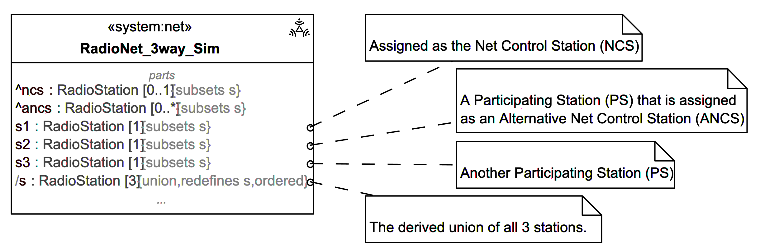
A typical Radio Net has one Net Control Station (NCS), responsible for coordinating each net session and relaying radio messages between participating radio stations, and one or more Alternate Net Control Stations (ANCS). As a simplification in this model here, the NCS station does not participate as a final recipient of radio messages. Non NCS stations are denoted here Participating Stations (PS).
The simulation model is a 3-Way Radio Net, with one Net Control Station (NCS) and two Participating Stations (PS), one of which is assigned as an Alternate Net Control Station, although the functionality and role of the ANCS is not otherwise explored.
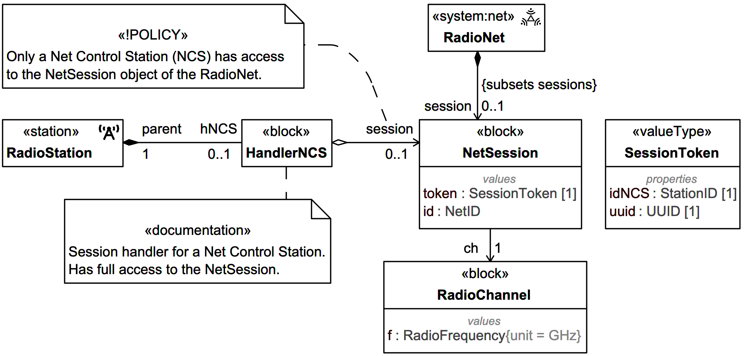
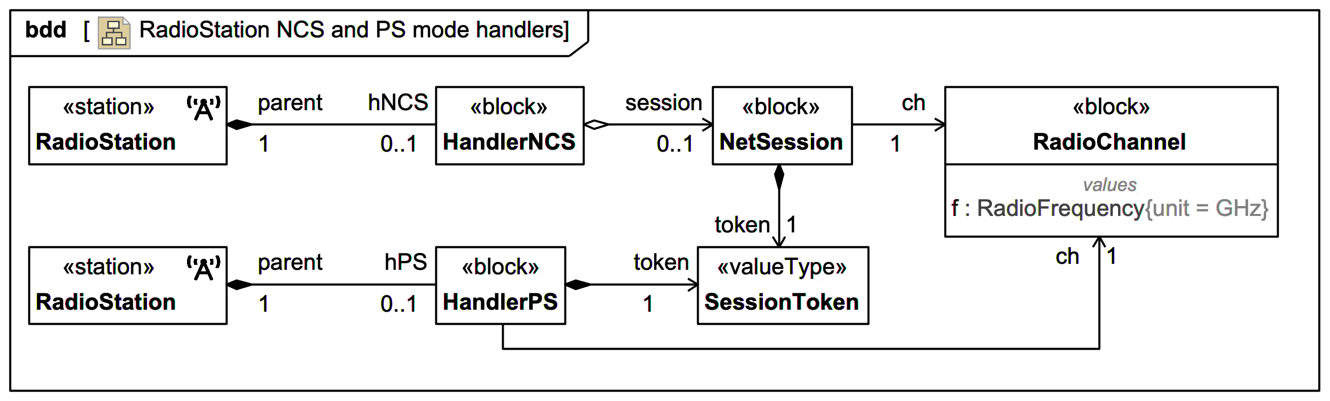
Only the NCS has full access to the NetSession object, which includes information on the radio channel to be used, such as a radio frequency for the session.
As a simple secure messaging model, each NetSession is associated with a unique token (which has a UUID). Every message of any kind exchanged within the net during one session MUST carry a matching token to be accepted by a recipient.
One common principle of Radio Nets adopted in the model is the use of a scheduling channel separate from the main radio communications, which scheduling channel may be via a communication channel other radio. In this model scheduling messages are sent via an inout Port dedicated to scheduling messages, and routed via a hub.
The use of a scheduling message routing hub and Ports enables decoupling of the RadioStation objects and offers a security advantage, in the sense that a RadioStation object does not need to have a reference to other RadioStation objects, as demonstrated at:
Note therefore that a PS - which does not have an object reference to the NCS - does not have access to the NetSession object managed solely by the NCS, or to other potentially sensitive information managed by the NCS such as messaging logs.
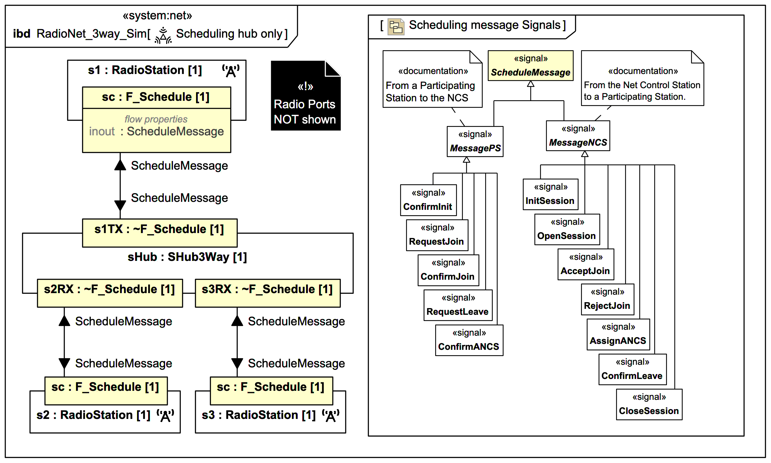
On initialisation of a session, the NCS shares via the separate scheduling channel selected information with every PS, such as the session token and the radio frequency of the channel for the session. There is a session opening and PS joining sequence before radio message transmissions may commence.
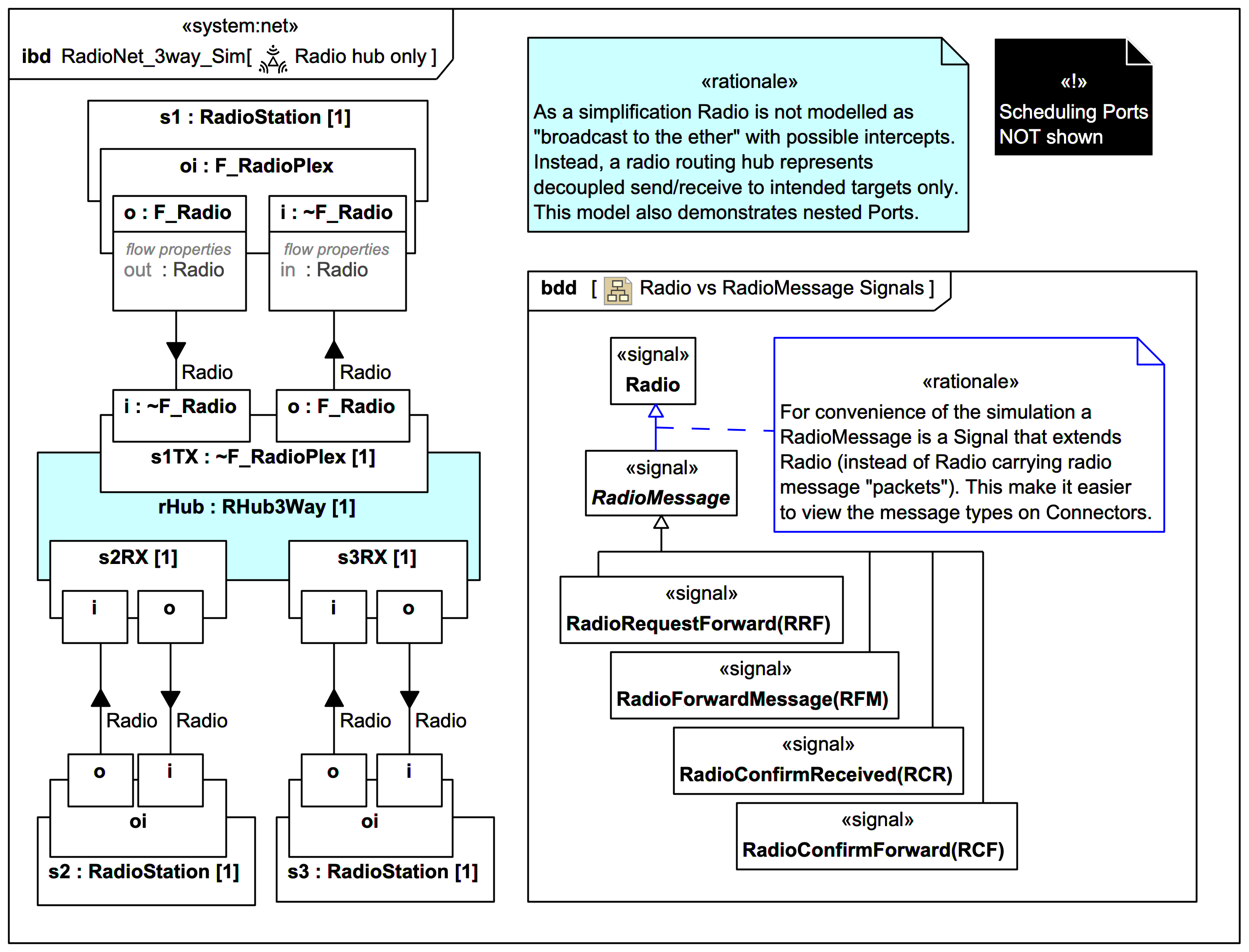
In a real world situation, radio transmissions, whilst possibly highly directional, could be intercepted by many different radio stations because "broadcast to the ether". As a simplification, it was decided not to include this possibility in the model. Rather, an intermediary radio routing hub is used, which is also used to demonstrate nested Ports.
In a real world situation, radio transmissions typically "carry" a radio message within them (the precise details depend on whether digital or analog and the mechanism used). This invites modelling the transmission of radio signals separate from message "packets" they carry. However, this makes it harder to follow in Magic Model Analyst® (Cameo Simulation Toolkit®), since the animation of Signals along Connectors does not display their content. Therefore, a compromise was used; there is a Signal type Radio - which defines the type of the FlowProperty on radio ports - and an extending Signal type RadioMessage, which defines a family of radio messages. (An alternative approach would be to model the radio messages as Blocks carried by any Radio Signal, but this is not as animation-friendly).
For simplicity, each radio transmission is assumed to be analog and at a single pre-agreed channel frequency.
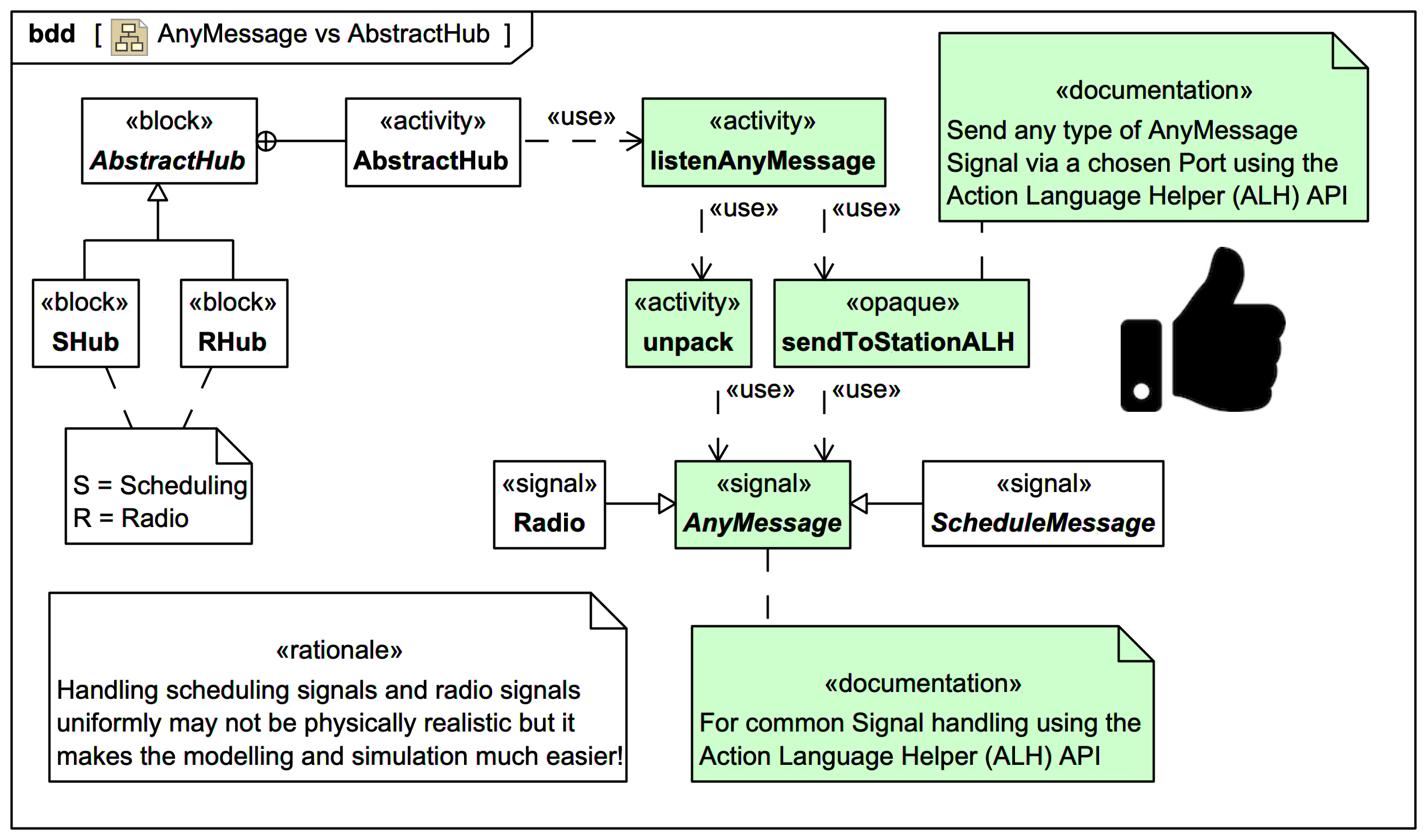
The SHub scheduling message routing hub and the RHub radio message routing hub both extend an AbstractHub, which uses the Action Language Helper (ALH) API via Groovy scripts to offer a convenient uniform programmatic Signal routing system for AnyMessage, where ScheduleMessage and Radio (and thus RadioMessage) are both specific sub-types of AnyMessage. This modelling choice may not be physically realistic (since the scheduling messages channel could be completely separate from the radio messaging channel), but it greatly simplifies the modelling and simulation. A similar ALH-based programmatic Signal handling strategy is used in the radio Transmitter and Receiver within each RadioStation as we'll see later.
Some aspects of the model are contrived merely to demonstrate various aspects of SysMLv1. For example, for demonstrating listening for messages, sometimes StateMachines with Transition effects are used and sometimes Activities with AcceptEventActions are used, although in most cases either could be used.
Much of the functionality of each of NCS and PS modes is captured by a handler, which acts in coding terms as friend to its parent RadioStation, and thus has free access to the values and operations of its parent RadioStation. An NCS RadioStation has a HandlerNCS and a PS RadioStation has a HandlerPS. For the sake of demonstration, the HandlerNCS uses primarily Activities with AcceptEventAction when listening and the HandlerPS uses a StateMachine with Transition effects.
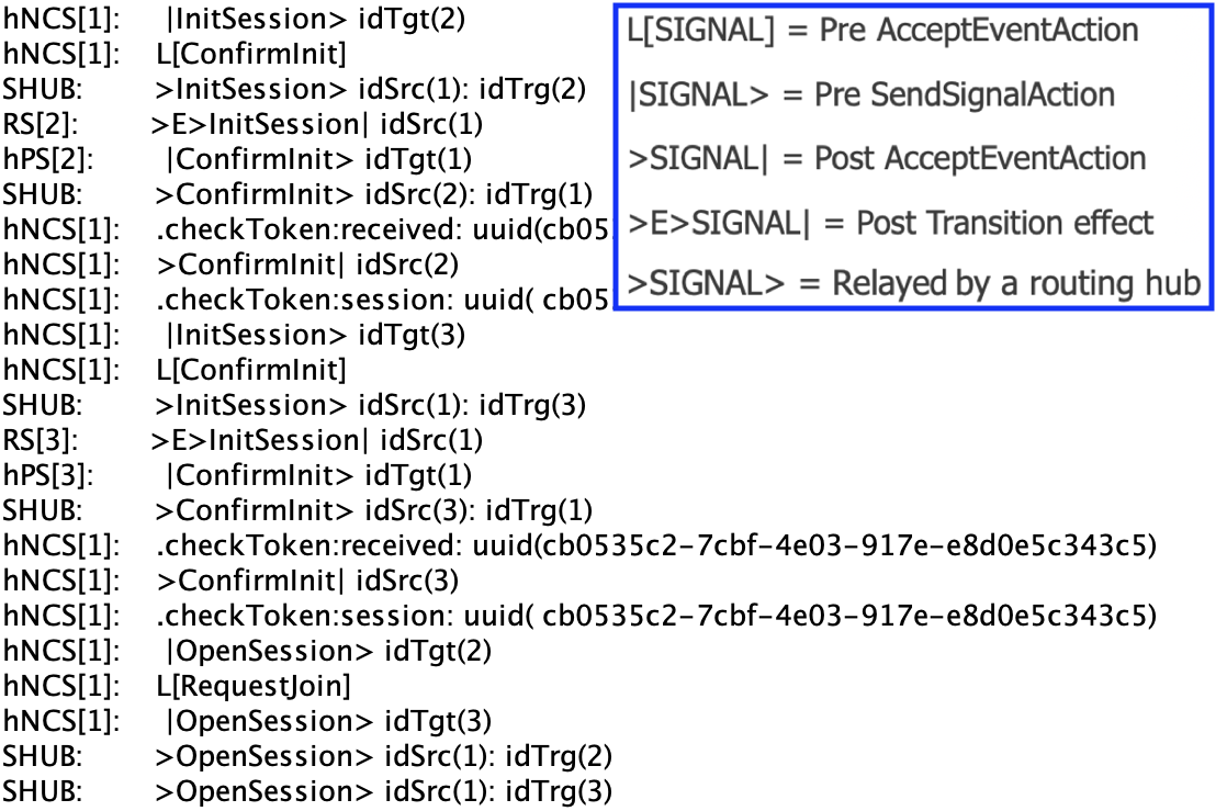
About the Signal "echo" console diagnostics
One slightly unusual - but extremely useful - thing you'll see in this model is the use of organised echo diagnostics to the simulation console to help track Signal sending, listening, receiving, and Transition effects. It's a bit of extra modelling work, but definitely of benefit for this particular messaging oriented Radio Net task. There are many supporting echo Operations that make it easier. They leverage additional families of SysML Enumerations SignalKindS and SignalKindR (which both extend SignalKind) corresponding to the various Signal types; these too represent a slight maintenance overhead but are worth the extra effort, as we'll see when we inspect some console output. BTW: These additional Signal echo console diagnostics play a different role from the Cameo Simulation Toolkit's Signal animation and complement it.
On scripted OpaqueActions/Behaviors vs graphical modelling using low-level SysML setters/getters
For pedagogical reasons this model shows quite a bit of low-level (and some might consider tedious) Activity modelling using graphical SysMLv1 modelling constructs such as ReadSelfAction, ValueSpecificationAction, ReadStructuralFeatureValueAction, AddStructuralFeatureValueAction etc. In many cases, these can be handled more conveniently using scripting with a language like Groovy in OpaqueActions and reusable OpaqueBehaviors, and this is demonstrated too. However:
In general, it is safer to feed generic OpaqueBehaviors with values pulled from the model using basic SysML like ReadStructuralFeatureValueAction, even if it is a bit tedious, because if you change the accessed Property name the simulation model won't break.
Encapsulate the tedium!
The Webel Radio Net model makes a lot of use of quite low-level Activities to capture reusable aspects. This repays itself many times over! As soon as you identify something you think could be reused throughout the model, encapsulate it as a reusable Activity (or OpaqueBehavior)! It will make your modelling ultimately faster, the logic cleaner, and testing the simulation easier. Everything will be much easier if you take the time up front dealing with the little stuff systematically. Got a large Activity Diagram in a spaghetti tangle? It almost always means you need to encapsulate some reusable aspects.
What the Webel Radio Net model is NOT!
The emphasis of the Webel Radio Net model is on how to model and simulate a realistic port-based messaging system in Cameo Simulation Toolkit with SysMLv1, and focusses almost entirely on the "design" (or "implementation") layers and the Model-Based (MB) aspect of Model-Based Systems Engineering (MBSE). It is not:
- A demonstration of a formal Systems Engineering (SE) methodology.
- A demonstration of a formal SE functional analysis breakdown or allocation.
- A demonstration of separation of "problem" space from "solution" space.
- A demonstration of interface matching between a logical (aka conceptual) component layer and a design and/or implementation layer.
- A demonstration of Requirements Engineering and analysis.
- A study of Use Case drill-down.
- A one-size-fits-all guide to organising your own SysML models.
Many of the aspects one might usually handle via Requirements Analysis are instead indicated using editorial Comments (which can appear in any Diagram type) with custom stereotypes using the Webel convention of prefixing editorial stereotype keywords with a '!', such as: «!POLICY», «!CONVENTION» etc.
Many of the modelling strategies used are also explored as individual abstract tasks under the tutorial. If you struggle with any of the more complex Radio Net model examples, consider inspecting these cross-linked simpler abstract examples: